The Arbalist Guild

Would you like to react to this message? Create an account in a few clicks or log in to continue.

Crossbows - Everything about Building, Modding, and Using your Crossbow Gear

Latest topics

» 12th Century Chinese Crossbow Chronographed
by stuckinthemud1 Fri Nov 24, 2023 3:50 pm

» Crossbow Stock
by kenh Tue Oct 31, 2023 6:19 am

» Colletiere a Charavines continuing experiment
by stuckinthemud1 Sat Oct 07, 2023 5:36 am

» Cocking - how
by stuckinthemud1 Thu Aug 03, 2023 4:24 am

» Questions around heavy crossbow lath buildin
by stuckinthemud1 Wed Apr 26, 2023 1:10 am

» Arab Crossbow
by stuckinthemud1 Tue Apr 25, 2023 7:57 am

» prod angle, and lever trigger for sale anyone?
by stuckinthemud1 Mon Mar 20, 2023 5:54 am

» flexible string
by jasper1978 Mon Mar 20, 2023 1:25 am

» [solved]Skane/Lillohus crossbow thread
by stuckinthemud1 Sun Mar 19, 2023 7:44 am

» jens sensfelder
by jasper1978 Wed Mar 08, 2023 11:58 pm

» 400lb Windlass crossbow bolts weight and accuracy shooting high.
by stuckinthemud1 Sun Mar 05, 2023 2:53 pm

» Codex Löffelholz crossbow
by stuckinthemud1 Tue Jan 24, 2023 4:14 pm

» Digitar prodsc
by stuckinthemud1 Sun Jan 15, 2023 2:42 pm

» Troubleshooting
by Andy. Fri Jan 06, 2023 12:29 pm

» Wood Prods
by stuckinthemud1 Fri Dec 30, 2022 12:47 pm

» Colletiere a Charavines crossbow
by stuckinthemud1 Fri Dec 30, 2022 8:54 am

» Simplified Löffelhotz speedloader
by stuckinthemud1 Fri Dec 09, 2022 4:05 pm

» Fiberglass H-bows
by c sitas Sat Nov 12, 2022 8:44 am

» Bad Antler
by drawknife Sat Nov 12, 2022 3:48 am

» Anyone make their own bolts?
by Juniper Mon Oct 17, 2022 8:20 am

» Josef alm in English
by Juniper Sat Oct 15, 2022 4:22 am

» Qin/Han lock drawings
by kenh Fri Sep 23, 2022 8:16 pm

» stirrup dimensions?
by stuckinthemud1 Thu Sep 01, 2022 1:49 pm

» Skane/Lillohus lockbow information needed
by stuckinthemud1 Sun Aug 14, 2022 6:23 am

» need help contacting le musee Dauphinois Grenoble
by stuckinthemud1 Sat Aug 13, 2022 3:22 pm


+7
asken92
hullutiedemies
c sitas
Gnome
Anatine Duo
jaeger22
Hermit
11 posters

    RDT experiments

    avatar
    jaeger22
    Workshop Savvy

    Did you see my tool collection?


    Workshop SavvyDid you see my tool collection?


    Posts : 153
    Join date : 2013-03-15
    Age : 75
    Location : Orlando, FL

    RDT experiments Empty RDT experiments

    Post by jaeger22 Mon Jan 19, 2015 4:53 am

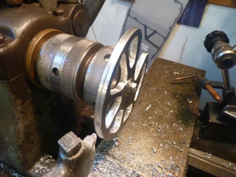
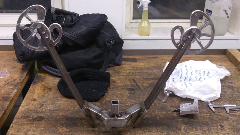
    I am inspired by  Patandjliand and Ali but want to incorporate some ideas of my own. I started with the cams. I have an old lathe and mil but neither cuts shapes well that are not either round or straight. Strait lines on the mill are easy but cam shapes, not so much. So I redesigned the cams to use round shapes except for cut outs that are just to lighten the cam. I don't know if they will yield the kind of draw force curve I am looking for yet, I need to build limbs and make strings, but here is what I have so far:
    RDT experiments P1020117_zps760c2916

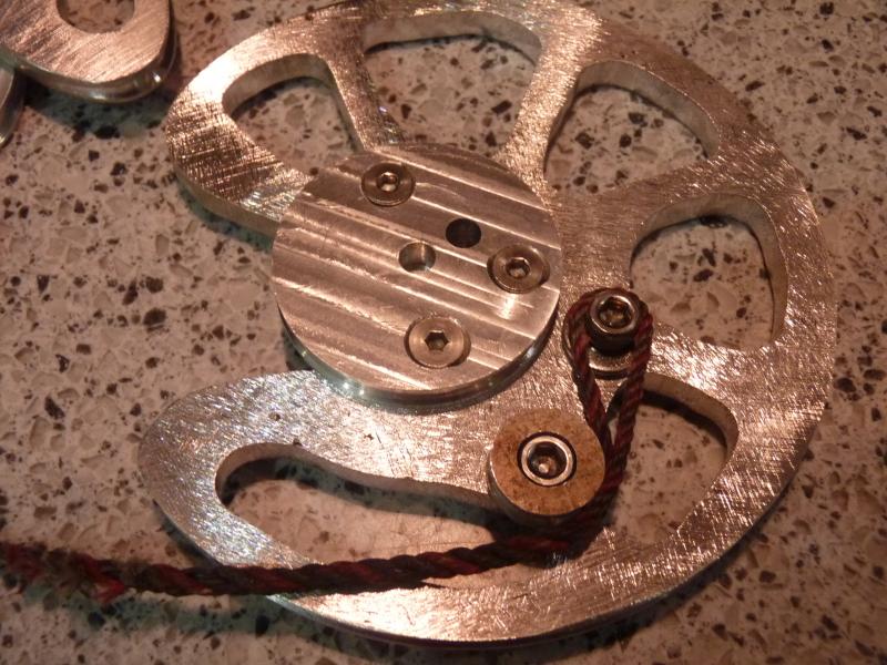
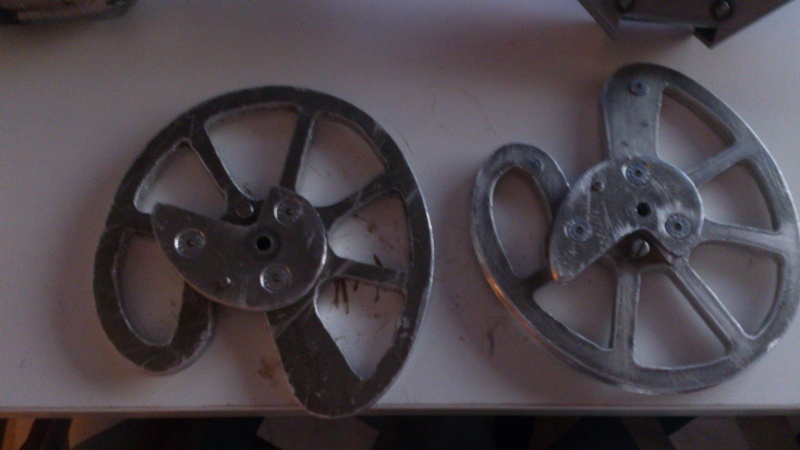
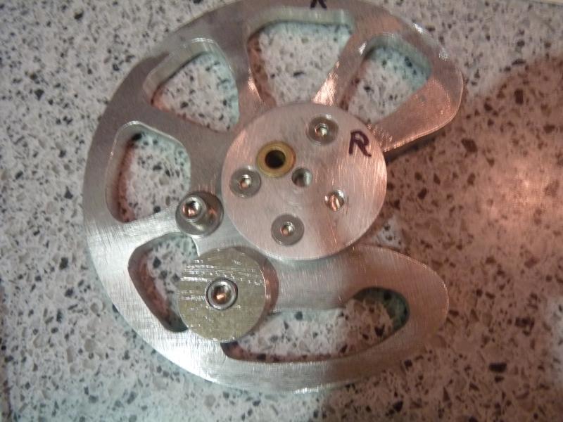
    Instead of one elongated power cam I am using a 2 piece cam consisting of one eccentric round main cam and a smaller offset "button" to give similar geometry to the single cam. This allowed me to machine the cam parts on the lathe,
    The main or string cam is actually a perfect circle around the axle except for the cut out notch for the string attachment.
    More to come. ..
    avatar
    Hermit
    Workshop Savvy

    Did you see my tool collection?


    Workshop SavvyDid you see my tool collection?


    Posts : 245
    Join date : 2013-09-10

    RDT experiments Empty Re: RDT experiments

    Post by Hermit Mon Jan 19, 2015 11:30 am

    Hi Jaeger,I am following your cam construction with interest.I am finishing my cams at the moment.The problem that I have,is machining the groove in the outer edge of the cam.I don't have access to a mill,and have tried the method that uses an angle grinder to cut the groove.I was not happy with it.The groove is 6mm(quarter inch as near as dammit)wide,and when centred leaves very little either side,The aluminium cutting disc(1/4ins.)cut oversize,so I didn't pursue it.I have ideas about how to do it using Ali's method with a drill press,but I don't fancy trying to feed a cutter into that size and depth of groove by hand so I need to make some sort of feed table that that can be fed into the cutter in small increments,taking big bites out of aluminium while holding the cam does not appeal!.I have started filing the outer groove by hand,and it works,but the time it takes!if I needed a hobby before,I sure as shooting don't need one now!,but I still think it'll be quicker than making a special fixture.I thought when I undertook this project that the cams were going to be problematic,and so it's proven to be the case.
                                                                   Hermit.
    avatar
    jaeger22
    Workshop Savvy

    Did you see my tool collection?


    Workshop SavvyDid you see my tool collection?


    Posts : 153
    Join date : 2013-03-15
    Age : 75
    Location : Orlando, FL

    RDT experiments Empty Re: RDT experiments

    Post by jaeger22 Tue Jan 20, 2015 4:13 am

    Hermit, yes I agree the groves are a major pain. That is exactly I chose to change the design to round parts! It is relatively easy to cut the grooves on the lathe. Like this;
    RDT experiments P1020065_zps012b4376

    I think that if I didn't have the lathe I might try mounting round parts in a drill press and then fab some kind of cutter. Sort of a make shift lathe. Or like Patandjliand and Ali, put some kind of cutter in the drill press and rig a platform to hold the part at the right level.
    I did have to continue the groove around the bends into the notch and I did that by hand using rat tail files and chain saw sharpening files. Even that small area was a tedious so I feel your pain doing the entire outside by hand. My string cams are 5.5" in diameter so just over 17" in circumference. Times two cams is 34" of grove to cut out by hand. tongue And then you have to do the power cams! Way too much hand work for me so it is worth figuring out some way to let the machines do the work! scratch
    Now I have to do some kind of test rig so I can see if my cam design works.
    Please keep us up to date on your progress. Pictures!
    Gnome
    Gnome
    Crossbow Junkie

    I live here!


    Crossbow JunkieI live here!


    Posts : 451
    Join date : 2011-10-16
    Age : 60
    Location : North Georgia

    RDT experiments Empty Re: RDT experiments

    Post by Gnome Tue Jan 20, 2015 9:20 am

    Awesome progress! I'm also jumping on the reverse-draw bandwagon. I've got two avenues I'm exploring concurrently: repurposing cams and limbs from an old flea-market find compound bow, and designing and cutting a multi-level laminate structure for a modern cam build. I'm working at 50% scale until I figure out what I'm doing. Keep posting updates!
    Gnome
    avatar
    jaeger22
    Workshop Savvy

    Did you see my tool collection?


    Workshop SavvyDid you see my tool collection?


    Posts : 153
    Join date : 2013-03-15
    Age : 75
    Location : Orlando, FL

    RDT experiments Empty Re: RDT experiments

    Post by jaeger22 Wed Jan 21, 2015 5:19 am

    Gnome, glad to hear you are joining in the fun! With Hermit, that makes at least 3 of us working on it.
    I thought about the used compound bow limbs and cams as well but decided it would be too hard to find ones that were suitable for RDT. But some of the newer ones might work. Keep in mind that we want to dramatically increase draw length so the ones on the RDT are HUGE and the ratio between the smaller power cam and the large string cam is very high. We will also need MUCH stronger limbs than typically found on a compound due to the gear reduction and higher pull weights we typically are looking for. Still some of the newer hand held bows are approaching this with short horizontal limbs and big cams. Please post pictures of what you find and how they work out.
    I am almost finished with my test rig for testing the cams and getting data on the limbs. I know the limbs will need to be much thicker and stronger and with the data I gather from this experiment I should be able to calculate the required thickness for the final design. scratch 
    Here is what the test rig looks like so far:
    RDT experiments P1020119_zpse61a6af8
    Anatine Duo
    Anatine Duo
    Tinkerer

    If there is a will, there is a way.


    TinkererIf there is a will, there  is a way.


    Posts : 65
    Join date : 2013-10-07
    Location : Muskoka, Canada

    RDT experiments Empty Re: RDT experiments

    Post by Anatine Duo Wed Jan 21, 2015 6:12 am

    This is exciting!  I bit off too many projects and can't build-along but...

    I have some  thoughts on cams for home-builders:

    my Barnett Thunderbolt has 2" round pulleys with the axle near the rim.  Power pulley is the same diameter, it's a simple double pulley

    not great F/D but you get let-off and draw (scale up obviously) and very easy to make


    Last edited by Anatine Duo on Wed Jan 21, 2015 6:56 am; edited 1 time in total (Reason for editing : oops)
    Gnome
    Gnome
    Crossbow Junkie

    I live here!


    Crossbow JunkieI live here!


    Posts : 451
    Join date : 2011-10-16
    Age : 60
    Location : North Georgia

    RDT experiments Empty Re: RDT experiments

    Post by Gnome Wed Jan 21, 2015 9:26 am

    Jaeger, I see you are anchoring your cable on the axle in your mockup- Is that how you're going to do it on the real thing? That's what I was planning and it seems the easiest solution, but I see most commercial RDs have them anchored down further on the limbs. I wonder how much difference that makes?
    Regarding the old bow parts I'm messing with, I'm planning a pistol-size weapon with a power stroke of no more than 11 inches, so the size of the cams and the stiffness of the limbs, which I'll shorten, should be closer to optimal.
    Gnome
    avatar
    jaeger22
    Workshop Savvy

    Did you see my tool collection?


    Workshop SavvyDid you see my tool collection?


    Posts : 153
    Join date : 2013-03-15
    Age : 75
    Location : Orlando, FL

    RDT experiments Empty Re: RDT experiments

    Post by jaeger22 Thu Jan 22, 2015 5:49 am

    Anatine Duo wrote:my Barnett Thunderbolt has 2" round pulleys with the axle near the rim.  Power pulley is the same diameter, it's a simple double pulley
    Yep, this is what was on the original compound bows and I expect works fine for conventional compound xbows. But for the reverse draw I am thinking we need the small power cam / large string cam, to get the longer draw with limited limb movement.
    Gnome wrote:Jaeger, I see you are anchoring your cable on the axle in your mockup- Is that how you're going to do it on the real thing? That's what I was planning and it seems the easiest solution, but I see most commercial RDs have them anchored down further on the limbs. I wonder how much difference that makes?
    Yes I plan to just use the axle just because it is simpler. The advantage of using a separate anchor down on the limb is that it is centered so less torque on the cam and less twist on the limb. But I am thinking it would be a pain to do on the split limbs so I plan to use the KISS principle (Keep It Simple Stupid). It has served me well over the years! Laughing 
    A lot of hand bows use split or "Y"cables so they can tie to the axle on both sides and keep the pull even. I was thinking about that but realized with the pass through the stock and the short distance between cams, there was just not enough room. Neutral  So back to KISS! Laughing
    Anatine Duo
    Anatine Duo
    Tinkerer

    If there is a will, there is a way.


    TinkererIf there is a will, there  is a way.


    Posts : 65
    Join date : 2013-10-07
    Location : Muskoka, Canada

    RDT experiments Empty Re: RDT experiments

    Post by Anatine Duo Thu Jan 22, 2015 10:36 am

    Yes I agree we should keep the limb movement minimal, so coax small diameter power pulley is an option.

    Your work is awesome. I am too lazy to  engineer radical cams so looking for a quick solution so we can see more homebuilds

    The feathery thin 5" cams on my Diamond would take a heroic effort to duplicate in a home shop
    avatar
    jaeger22
    Workshop Savvy

    Did you see my tool collection?


    Workshop SavvyDid you see my tool collection?


    Posts : 153
    Join date : 2013-03-15
    Age : 75
    Location : Orlando, FL

    RDT experiments Empty Re: RDT experiments

    Post by jaeger22 Thu Jan 22, 2015 11:36 am

    So I got the test bow mounted to my bow measuring rig and was able to plot the draw force curve.
    Bow measuring rig:
    RDT experiments P1020120_zps9ub7hssm


    Draw force curve:
    RDT experiments P1020122_zpsgx1f93mz

    This will work but I was hoping for more of a flat table top effect. The back or right side looks OK to me with 28% let off which is fine for a crossbow I think but I would like it to "load up" faster on the front end. Also I only got 18" of draw when I was expecting 20". I think I have my string lengths off a bit. So a couple of things to play with.
    The weight is stupid weak at this point. Peak is 18.5 LB! Shocked I expected that with the gear reduction effect in the cams it would be weak but not this much. Limbs are made from 1/4" fiberglass from a boat cover bow. But it might be OK in the end. I plan to epoxy a second 1/4" layer for a total of 1/2" thickness. If I remember right, bending force goes up with the cube of thickness so that should yield something in the range of  148 LB peak weight. I will be happy if it is close to that. 
    More experiments to come! Jam 
    And hopefully a decent crossbow at the end of this adventure!
    avatar
    Hermit
    Workshop Savvy

    Did you see my tool collection?


    Workshop SavvyDid you see my tool collection?


    Posts : 245
    Join date : 2013-09-10

    RDT experiments Empty Re: RDT experiments

    Post by Hermit Fri Jan 23, 2015 6:42 pm

    Jaeger my friend,I hate to have to tell you this,but by changing the shape of your cams,you have changed them from cams to pulleys,with all the advantages of pulleys,but none of cams.I have learned much during the time I have been a member of this forum,for instance,that in order to obtain maximum power,you need the longest draw you can get,and the fastest arrow (bolt) speed,and for a bonus,string acceleration if you can get it!
                                             There are 2 types of cam,constant motion and accelerated motion.the function of these 2 types of cam is well described by their designation.The cams used on Patandjali's bow(the bow we all fell in love with,and the inspiration for the interest in this type of crossbow)are accelerated motion cams.Their ovoid shape and off centre pivot shows this.By making them concentric,you have lost their ability to provide string acceleration,which is going to reduce arrow speed and power.Please don't take this as a criticism,it is not intended to be one,simply a reminder to anyone reading your posts and intending to build an R.D.T. crossbow,that while building these cams is made simpler by changing their shape to concentric they are going to lose the advantages that a cam has over a pulley.
                             Hermit.
    avatar
    jaeger22
    Workshop Savvy

    Did you see my tool collection?


    Workshop SavvyDid you see my tool collection?


    Posts : 153
    Join date : 2013-03-15
    Age : 75
    Location : Orlando, FL

    RDT experiments Empty Re: RDT experiments

    Post by jaeger22 Sat Jan 24, 2015 5:24 am

    Hermit wrote:Please don't take this as a criticism,it is not intended to be one,simply a reminder to anyone reading your posts and intending to build an R.D.T.

    Hermit, no problem at all, please do point out when you see me doing something stupid! Smile 
    However in this case I think that it is just that I failed to make a few points clear.
    First, as you know, there are two cams involved with my design as well as Patandjali's bow and most commercial designs that I have seen. The outer wheel or cam for the string and the smaller power cam. You can get a "cam" effect from either the string wheel or the power cam or both. Notice that on Patandjali's cams the outer wheel is darn near round except for the large notch cut out of it. And that the axle is in the center or very near. All or nearly all of his "cam" effect is coming from the power cam. I have done the exact same thing but I used round parts to achieve it with a two part power cam.
    So to illustrate, look at the location of the brass bushing in this cam. Note that is in the center of the large wheel and way off center of the smaller wheel.
    RDT experiments P1020126_zpsdxmxpu7d

    That makes the small wheel eccentric or a "cam". In addition note the second smaller wheel below. The string goes around that so it becomes VERY eccentric. You can see that here:

    RDT experiments P1020124_zpssrtrr0jc

    The two round parts together form a shape very near Patandjali's but without the cut out in his.
    There are two factors that make RTD or any compound bow faster. The pulley effect allows long string pull with small limb movement. This allows the limb to recover more quickly due to the shorter arc it has to travel. The more important effect is the cam action action that allows the pull weight to build up sooner and then flatten out and finally to drop off. This allows the bow to store more energy and that energy is what makes the arrow go. This total stored energy is by far the most important factor in arrow speed. As you point out if I just used round cams for both string and power cam, the second effect would not happen. But you can see that it IS happening in this draw force curve. I increased the size of the small cam or button to get the higher curve. I included an approximation of the draw force curve we would expect to see from a recurve bow. If I just used pulleys I would expect the same shaped curve from mine. Note the huge difference in the area under the curve which is the stored energy between that curve and the plot from my bow and cams.

    RDT experiments P1020125_zpsci6dfrdd

    So basically the data so far shows that is working and giving the results I was shooting for in my design. But the final proof of course will not come until I can send arrows down range and I have a lot to go before that happens.  tongue
    Thoughts? 
    John
    Anatine Duo
    Anatine Duo
    Tinkerer

    If there is a will, there is a way.


    TinkererIf there is a will, there  is a way.


    Posts : 65
    Join date : 2013-10-07
    Location : Muskoka, Canada

    RDT experiments Empty Re: RDT experiments

    Post by Anatine Duo Mon Jan 26, 2015 7:55 am

    I think he means that your FD curve looks smooth like eccentric pulleys


    Radical cams have a squarer area under the curve


    You can adjust all kinds of fd the way you made it!  Cool!
    avatar
    Hermit
    Workshop Savvy

    Did you see my tool collection?


    Workshop SavvyDid you see my tool collection?


    Posts : 245
    Join date : 2013-09-10

    RDT experiments Empty Re: RDT experiments

    Post by Hermit Mon Jan 26, 2015 10:42 am

    Thanks for your second posting,I had not spotted how eccentric the small cam was on your first.One cam makes for a fairly predictable situation.Add another,and the possibilities increase.I have wondered who worked out the cam configuration on Patandjali's bow.Was it done with experiments,and is it the optimimum design,was it a copy of cams from a commercial bow?However it was arrived at,it seems to work,and work well.Your design simplifies machining,and that has to be a plus.I have so much invested in my cams,both money and time,that I am going to continue looking for a simple and accurate way to machine the grooves.I think I see a way to do it using a woodworking router mounted horizontally,instead of vertically as is usual, using a ball ended cutter.
                                                     As the cam has to be fed into the cutter while I am holding it,I need to devise a way to feed it into the cutter in small increments,in order to do it safely.Cams should be cams,not projectiles!.I think I see a way to achieve it simply,and with the resources I have,material for a future posting here............
                                                  Hermit.
    avatar
    c sitas
    Crossbow Junkie

    I live here!


    Crossbow JunkieI live here!


    Posts : 547
    Join date : 2012-11-24

    RDT experiments Empty experiments

    Post by c sitas Mon Jan 26, 2015 11:45 am

    Hermit ,would it be possible to make a wooden adjustable fence,so as to limit the depth of cut. You'd have the cam riding the fence so to speak and only a certain amount would stick out to be cut.Where your holding by hand ,go very slight at a time , Your fingers will last longer this way.
    hullutiedemies
    hullutiedemies
    Workshop Savvy

    Did you see my tool collection?


    Workshop SavvyDid you see my tool collection?


    Posts : 202
    Join date : 2012-07-03
    Location : Fennoscandia

    RDT experiments Empty Re: RDT experiments

    Post by hullutiedemies Mon Jan 26, 2015 1:54 pm

    Anatine Duo wrote:. I am too lazy to  engineer radical cams so looking for a quick solution so we can see more homebuilds

    The feathery thin 5" cams on my Diamond would take a heroic effort to duplicate in a home shop

    You could allways use straight levers like the "Woodland Flipper". Shape back end of the lever like cam and rig cable from there to opposite limb. No reason why it should not work.
    Could be made out of wood or fiberglass.
    Might not really even need a cam shape- the changing string & cable angles with straigh levers should be nough.

    ( come to think of it - been there, done that "F/D-curve is fat like a singing lady. This is a true compound bow.")
    avatar
    jaeger22
    Workshop Savvy

    Did you see my tool collection?


    Workshop SavvyDid you see my tool collection?


    Posts : 153
    Join date : 2013-03-15
    Age : 75
    Location : Orlando, FL

    RDT experiments Empty Re: RDT experiments

    Post by jaeger22 Mon Feb 02, 2015 4:35 am

    So I was planning to planning to weld up a steel limb holder or cradle just like Patandjali and Ali did but I got to looking at some aluminum channel and angle I had in the shop and wondered. . . .

    RDT experiments P1020127_zpswfjrh0a4

    Yep, another experiment. (why be normal) Very Happy 

    Here is what it looks like so far:
    RDT experiments P1020130_zpsyloke6if


    I plan to mount them on the sides of the stock with two bolts going all the way through. Here is one side laid on a stock to give the idea:
    RDT experiments P1020133_zpslsj1bl0r

    I machined an aluminum pad with slots to hold the split limbs and a shallow wide slot on the bottom to fit the angle but have not made the top cap yet. Each cap will get a 5/16" bolt through the back and a 10-20 screw in the front to hold them and the limbs together. If this little side experiment does not work out I can always go back to the welded steel version. I am not sure if this will end up lighter or heaver. I depends on how much more non stressed material I can remove to get the weight down. I have to tread carefully there. . .
    This will be a slow week due to travel for work. Sad
    avatar
    Hermit
    Workshop Savvy

    Did you see my tool collection?


    Workshop SavvyDid you see my tool collection?


    Posts : 245
    Join date : 2013-09-10

    RDT experiments Empty Re: RDT experiments

    Post by Hermit Mon Feb 02, 2015 12:23 pm

    Looks good Jaeger,I'm willing to bet it'll work.Instead of using bolts to hold the 2 halves of the limb holder together,did you not consider welding?.The strongest shape there is,is a circle.I am considering using a similar approach for the limb holders,but instead of using square tubing,I intend to use round.I intend to secure both limb holders to the sides of the stock with screws into blind tapped holes in round metal bars going through the stock.I may inlet the side plates for a little extra strength but haven't got to that stage yet,so haven't made a decision.Patandjali's bow's limb holder has compound angles,but I think that simple wooden holding jigs for position can be made for tack welding the plates to the round metal tube(by the time they catch fire,the tack welds will be done,and it won't matter!)that's the plan,but as I'm not there yet,I can't give a progress report.
                                                                 Hermit.
    avatar
    jaeger22
    Workshop Savvy

    Did you see my tool collection?


    Workshop SavvyDid you see my tool collection?


    Posts : 153
    Join date : 2013-03-15
    Age : 75
    Location : Orlando, FL

    RDT experiments Empty Re: RDT experiments

    Post by jaeger22 Tue Feb 03, 2015 4:22 am

    Yes welding is a very good idea. Sadly I do not have a way to weld aluminum. Sad I have a stick welder and can weld steel but aluminum, not so much. . .
    Yes tubing is the strongest for unidirectional loads. However the loads here are front to back in more or less one direction. I am thinking rectangular tubing or two round tubes side by side would work well. But lots of ways to skin that cat.
    I would love to see what you come up with. Please post. With pictures! Very Happy
    I think the riskiest part of this experiment so far is the limbs. They are made of two thickness of 1/4" fiberglass bar glued together with high strength epoxy.  I give it no more than 50% chance of working and not coming apart. But it is worth the experiment because if it works, I will have found a way to make extra heavy fiberglass bows suitable for RTD, for around $30 that anyone can do. If they explode, I will be placing an order to Bingham the next day for bowtuff, glue and laminates to make some serious limbs. Rolling Eyes 
    I wish I was in the now shop but I am headed for the airport. Sad
    avatar
    asken92
    Fresh Blood

    Doesn't mean
    I'm new to crossbows


    Fresh Blood Doesn't meanI'm new to crossbows


    Posts : 13
    Join date : 2012-11-26

    RDT experiments Empty Re: RDT experiments

    Post by asken92 Tue Feb 03, 2015 12:06 pm

    Since its a common subject on the forum right now to make RDT crossbow, ill thought i share my progress with you all and how i have done things.
    Its not all done yet, just roughly put it togheter today in school. but maybe it some clue of how i did it Smile
    https://i.servimg.com/u/f38/17/98/10/61/dsc_0114.jpg
    RDT experiments Dsc_0115
    RDT experiments Dsc_0115
    RDT experiments Dsc_0117
    RDT experiments Dsc_0118
    RDT experiments Dsc_0119
    RDT experiments Dsc_0215
    RDT experiments Dsc_0216
    RDT experiments Dsc_0217
    RDT experiments Dsc_0218
    avatar
    jaeger22
    Workshop Savvy

    Did you see my tool collection?


    Workshop SavvyDid you see my tool collection?


    Posts : 153
    Join date : 2013-03-15
    Age : 75
    Location : Orlando, FL

    RDT experiments Empty Re: RDT experiments

    Post by jaeger22 Wed Feb 04, 2015 3:25 am

    Nice work Asken!  cheers And thanks for the pictures. How do you plan to attach the cradle to the stock?
    What are you planning to use for the bow material?
    Please keep us informed of your progress.
    avatar
    asken92
    Fresh Blood

    Doesn't mean
    I'm new to crossbows


    Fresh Blood Doesn't meanI'm new to crossbows


    Posts : 13
    Join date : 2012-11-26

    RDT experiments Empty Re: RDT experiments

    Post by asken92 Wed Feb 04, 2015 12:59 pm

    Glad you enjoyed it! Wink i will post some more pictures but its suppose to be inside the stock, carving out the bottom of the stock and screw it in place if you know what i mean.. I havent made the stock yet since i am studying abroad and dont have access too a wood workshop. Nor the material. And the bow material is going to be springsteel from an old car. (yes, i know about the risk. I am just gonna have too be careful when i draw it up once.
    Only thing i am little bit curious about is what type of material to use for a string and how many strands i should need. 
    /Asken
    RDT experiments Dsc_0219
    RDT experiments Dsc_0220
    RDT experiments Dsc_0221
    RDT experiments Dsc_0222
    RDT experiments Dsc_0223
    RDT experiments Dsc_0224
    RDT experiments Dsc_0225
    avatar
    jaeger22
    Workshop Savvy

    Did you see my tool collection?


    Workshop SavvyDid you see my tool collection?


    Posts : 153
    Join date : 2013-03-15
    Age : 75
    Location : Orlando, FL

    RDT experiments Empty Re: RDT experiments

    Post by jaeger22 Wed Feb 04, 2015 6:30 pm

    Thanks Asken, yes I can see how it would mount in the stock now with the final bar in place as shown in the latest pictures. That should work. And your limbs look good to go. I may end up with steel but I want to experiment with various fiberglass types first to see if I can make them work.
    I made my string using Dacron B50, 22 strands each for the two power cam strings and 20 for the main string.  Nothing magical about those strand counts, just my guess. Yet another experiment! Very Happy I used braided serving material for the end loops and monofilament for the center of the main string.
    This kind of stuff:
    http://www.3riversarchery.com/brownell+b-50+dacron+waxed+bow+string+material_i4144X_baseitem.html

    I will take some pictures of them when I get home and also include my cheap (of course Rolling Eyes ) string jig.
    avatar
    Hermit
    Workshop Savvy

    Did you see my tool collection?


    Workshop SavvyDid you see my tool collection?


    Posts : 245
    Join date : 2013-09-10

    RDT experiments Empty Re: RDT experiments

    Post by Hermit Thu Feb 05, 2015 8:12 am

    Regarding the crossbow string,years ago,when I got into making mine,there was a simple formula which I used and which worked well.Take the bow draw weight(as an example 200lbs.)multiply that by 4(the safety factor)then divide that number by the breaking strain of the string material.Dacron is I believe 50lbs. per strand.Using this formula gives a string thickness of 16 strands.When the string is made,it should be well coated with beeswax.this was done by rubbing the beeswax onto the string,and then rubbing the string with a piece of leather.The friction of the leather on the string creates heat,which melted the beeswax into the string.String maintainance is important if you want to get good service from your string.When you have been using the bow for a while,you should be able to tell from the look of the string when it needs re-waxing,or a good rub to re-melt the beeswax.
                                           The bow that I built(almost 50 yrs ago)was a conventional crossbow,not a compound,with an aluminium prod of 150lbs draw weight with no upsweep on the prod.With a conventional bow,the depth of the bolt groove  dictates the placement of the prod and it's angle.Today,bow builders look for upsweep on the prod,and try hard to position the prod so that the string just kisses the stock as far along the deck as possible to reduce friction and loss of power.I didn't even think about it.Back then there was no internet,no crossbow forums and not much interest in crossbows.I am digressing a bit(or rambling,depending on your point of view)I put several hundred shots on that bow before I sold it,and the string was still good.The only repair I had to do to the string,was to re-serve the middle of the string because of wear on the serving by the nut.I used shoemakers thread for the serving.I believe waxing was the reason the string lasted so long.
                                                        Hermit.
    avatar
    jaeger22
    Workshop Savvy

    Did you see my tool collection?


    Workshop SavvyDid you see my tool collection?


    Posts : 153
    Join date : 2013-03-15
    Age : 75
    Location : Orlando, FL

    RDT experiments Empty Re: RDT experiments

    Post by jaeger22 Sun Feb 08, 2015 5:23 am

    Thanks Hermit! That is good info and food for thought. Keep in mind that the power cam strings will have higher loads than the main string by as much as 3 or 4 to 1 due to much lower mechanical advantage. But then there are two working together so that drops the total in half. Rolling Eyes Overall, maybe 150% of the main string but that is just a guess on my part.
    Here are the ones I made so far:
    RDT experiments P1020135_zpshtvdinir
    The long main string is 46" and I think it is a bit short. The cams don't roll out quite as far as they should.
    To the side, you can see my home made string jig. There are many ways to do this but this what I did. It is simple and cheap but you do have to drill a separate set of holes or have a separate base 2X4 for each string length (unless you machine in a long set of slots). This is set up for the 46. This design is intended to be used by wrapping the total number of strands around the outside and then turning the "wings" 90 degrees to form a rectangle. That gives clear access to serve 1/2 the strands to form the end loops. This will work if the "wings" have the center swivel hole EXACTLY centered between the two uprights. Otherwise you get slack. I found it a bit of a pain and much easier just to leave them locked in the long position and pull one bundle (1/2 the strands) out using the dowel mounted at an angle in the center.  I just use a rubber band or short piece of string to pull it out tight. That leaves me room to serve the other bundle in the middle. Then take the rubber band off, slide the string around the uprights 180 degrees and repeat. Then slide the string 90 degrees so the served sections are around the outside uprights and complete the serving operations.
    So you don't even need the "wings" just a 2X4 and two uprights and the center dowel. Mine only has them because that is the way I made them the first time. I think for the next string length I need I will get rid of them, For the uprights I used 1/2" ID tubing but about 10" long. But almost anything would work.

    Sponsored content


    RDT experiments Empty Re: RDT experiments

    Post by Sponsored content


      Current date/time is Fri Apr 26, 2024 10:06 am